• Welcome to OGBoards 10.0, keep in mind that we will be making LOTS of changes to smooth out the experience here and make it as close as possible functionally to the old software, but feel free to drop suggestions or requests in the Tech Support subforum!

Watch me build a Mini-Submersible

TWDeac

Resident Astrophysicist
Staff member
Joined
Mar 9, 2011
Messages
22,079
Reaction score
889
Location
Cincinnati, OH
As I mentioned in the gift thread a few weeks ago. I was fortunate enough to receive an OpenROV 2.8 kit for Christmas and wanted to document the process on the boards.

It is a fully contained submersible drone that can be controlled by a Xbox controller, can descend up to 300 feet, and streams live video back to your laptop. I've never been interested in an aerial drone, but when I saw this a few years ago, I put it on my wish-list. The OpenROV guys have a pre-built model coming out in late 2017, the Trident, but I wanted to build my own.

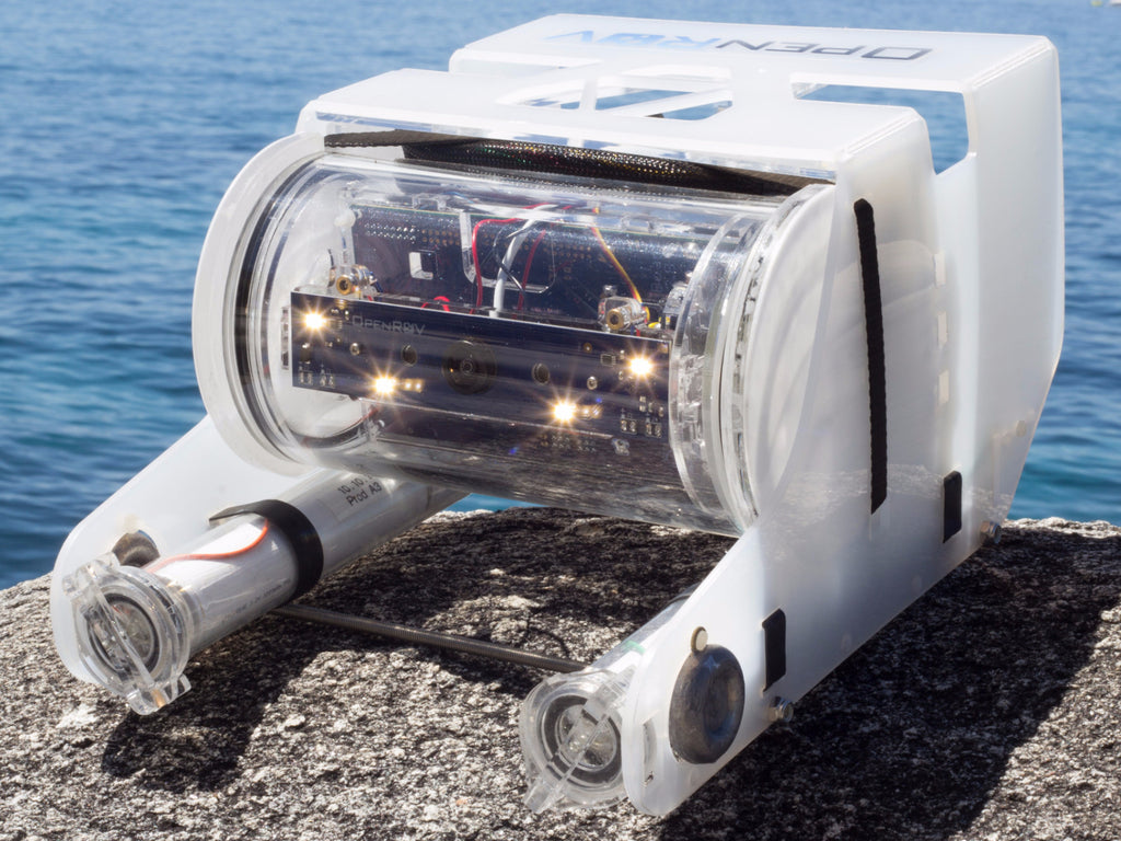
For those of you who don't care about the build process. This is what it looks like. I promise I'll have something similar to show you as well.

https://www.openrov.com/

IMG_7875_1024x1024.jpg


Xjt7USfh.jpg


Laser-cut acrylic pieces ready for assembly.

Wc1xXash.jpg


Arranging the acrylic pieces for the main body structure.

MQprl9Nh.jpg


First time ever using acrylic cement. I was certain that one of the local hobby shops would have this so I called around to a few. I may as well have been asking if they had meth in stock for the way these people responded. I ended up ordering it on Amazon. It has special shipping restrictions so it took a few weeks to get here.

I used Weld-On 4 which is a water thin version. https://www.amazon.com/Weld-Acrylic-Adhesive-Applicator-Bottle/dp/B0096TWKCW

Acrylic cement is a solvent that basically welds two pieces of acrylic together by softening the material and then fusing them as it evaporates. It is fantastic from a strength standpoint and once you get the hang of it, fairly easy to apply. Unlike super glue, if you spill a little extra on the face of one of your pieces, you aren't going to get an ugly pile of dried glue, the cement will evaporate away. The capillary effect is a big help as it effectively pulls the cement into the butted joint.

fp1bxmNh.jpg

Acrylic cement loaded into the syringe/bottle applicator.

yKN6xnBh.jpg


Cementing the vertical motor mount.

6ubuqxyh.jpg


Another view of the vertical thruster mount.

LyO9J2Uh.jpg


Cementing the port and starboard thruster support trusses.

snP6o8dh.jpg


Closer view of the cement application on the support trusses.

VRJx7kCh.jpg


I need more bench vises. This was my creative solution at supporting the camera mount while I cemented the camera supports.

rK5t4O4h.jpg


Cementing the skeleton of the ROV together.

zWnmqEYh.jpg


Finished camera mount and ROV skeleton.

mfHvorQh.jpg


Time to build the electronics assembly.

RwZ67Wch.jpg

gpay5UUh.jpg


Cementing the electronic mount end-cap

f6VhPAth.jpg


Pieces for the battery tube end-caps and a thruster/mount

XE1dpoOh.jpg


As you'll notice throughout the build. It calls for creative uses of unrelated parts. In this instance, you use the thruster shaft to align the battery tube end-caps properly. These are supremely important as they are all that stands between your Lithium-Ion batteries and the crushing depths.

gYcJjLyh.jpg


Completed battery end-caps and the acrylic components built thus far.
 
Sweet. Following.

Cool looking workbench. Is that in your garage or basement? I'm a shop nerd, so I'd love to see a photo of your workbench/shop.
 
Sweet. Following.

Cool looking workbench. Is that in your garage or basement? I'm a shop nerd, so I'd love to see a photo of your workbench/shop.

For TWDeac, it's both his garage and his basement. For now at least.
 
Sweet. Following.

Cool looking workbench. Is that in your garage or basement? I'm a shop nerd, so I'd love to see a photo of your workbench/shop.
I'm a huge fan of the workbench. It came out of an old PC manufacturing facility and it has a built in powerstrip and light. Perfect for this stuff. I'll take a picture of my shop space but I can't promise it will be organized. We are moving and shit is everywhere.
 
More progress!

5YHAkYxh.jpg


Cementing the two halves of the shore-side electronics box.


WaS3urQh.jpg


Constituent pieces of the electronics tube pressure-cap. This is the side with the backbone cable in it.

8WqROYSh.jpg


This was the first time that I was unsure of my cementing job. I was worried enough about it that I emailed the OpenROV guys. They said they've seen worse and that as long as there aren't any significant voids, it should be fine. As it turns out, cementing many large pieces together is difficult.

KbsxqCxh.jpg


Constituent pieces of the pressure-cap on the other side of the electronics tube. You can see the difference between the two.


M20G4tYh.jpg


This is the backbone cable for the whole ROV If you look back on the the first pressure cap parts photo, you'll see the slot for the cable connector. I am super gluing the metal shroud to the cap to temporarily hold it. The cable assembly is really stiff so this was fairly difficult. I took quite a few pictures during this step.


aaLQSL1h.jpg


More clamping. It is important that the metal shroud makes contact with the acrylic so I was particularly focused on this part.

fzTEYQfh.jpg


One can truly not have enough clamps in your workshop. I am cementing the white acrylic piece to the pressure cap in this step. Again, another very important step due the pressures involved in the use of the ROV at depth.

ncZSle8h.jpg


I did a pretty good applying to the cement to this one.

BJnAFCth.jpg


A good view of the cable channel.


gmukJpLh.jpg


This is a 2000 psi(2-ton) epoxy by Devcor that mixes as you apply it. I'd highly recommend it if you ever need epoxy for anything. My local Home Depot doesn't carry it, but my Ace Hardware does.

Ub12Sueh.jpg


Hole used to align all the pieces of the first pressure cap. It needs to be covered before potting the cable channel with epoxy.

W77xf2ph.jpg


This step involves forcing lots of epoxy into the cable channel to give it strength against pressure and to hopefully evacuate any air in the cavity.

Wge5WcZh.jpg


Fully potted but still wet.

fbnaO7oh.jpg


Drying time.

Kixj66Oh.jpg


Close-up of the a battery end-cap. The hole used to assemble the pieces must be potted as well.

zrLfEVVh.jpg


Epoxy applied and drying.


KpQ2qemh.jpg


This is a powerline adapter that is for home networking use for when you are unable to get decent wireless signal from your router or for some reason you don't want a router. You plug it into an outlet near your modem and hook an ethernet cable into it. You plug its twin into an outlet near your device that needs connectivity and plug an ethernet cable into it as well. From there, it uses the electrical cabling in your house to transmit data. The engineers at OpenROV are using it to transmit data in a similar fashion, just from the drone to your controlling laptop.

Don't have time to post more, but I figure this is a good cliffhanger.
 
So it communicates wirelessly underwater? That seems challenging. I thought it would require an umbilical of some sort.
 
Congratulations on a great build. Keep the pictures coming.

Reminds me of some HS projects made with acrylic plastic and pure acetone as the welding agent. It was necessary to get the gluing done before you forgot why and what you were gluing together.
 
So it communicates wirelessly underwater? That seems challenging. I thought it would require an umbilical of some sort.

I think the purpose of the powerline adapters is that it communicates over power cables/lines that are already there and being supplied instead of having to run some sort of cable just for data like cat5/cat6 or something (so no wireless involved, I'm pretty sure that wouldn't work under water at all). I'm a little unclear how these fit into the drone build though, is there one plugged in inside the drone to the power unit, and then an ethernet cable runs from that to an on-board adapter? and then you plug another one into some box/unit up top and run the ethernet cable from it to your laptop?
 
So it communicates wirelessly underwater? That seems challenging. I thought it would require an umbilical of some sort.
It uses a 100m tether both as a data pipeline and retrieval method. I'll get some good pictures of the attachment for you.
 
Enjoy the latest round of build pictures.


w4nkd1gh.jpg


Disassembly.

zaxGxEGh.jpg


More disassembly to get to the control boards.

eBXBHfxh.jpg


This is a circuit board created by the OpenROV engineers that interfaces with the shore-side powerline adapter board.

0eyQeHmh.jpg


Mated.. :naughty:

CR3dsjWh.jpg


I almost put this box together incorrectly but caught it before the cement hardened.

MTsN0Blh.jpg


This was a surprisingly difficult step. The electronics assembly doesn't sit completely flush and caused me all kinds of problems as I tried to make sure it was plumb and connected properly.

QtDkS71h.jpg


The BeagleBone black is the computer that drives the ROV. It has more powerful specs than a few of the computers I built when I was younger. Crazy.

Launched in April 23, 2013 at a price of $45. Among other differences, it increases RAM to 512 MB, the processor clock to 1 GHz, and it adds HDMI and 2 GB of eMMC flash memory. The BeagleBone Black also ships with Linux kernel 3.8, upgraded from the original BeagleBone's Linux kernel 3.2, allowing the BeagleBone Black to take advantage of Direct Rendering Manager (DRM).

BeagleBone Black Revision C (released in 2014) increased the size of the flash memory to 4 GB. This enables it to ship with Debian GNU/Linux installed. Previous revisions shipped with Ångstrom Linux.[34]

zEfxk9Oh.jpg


Ethernet cable connecting the powerline adapter to the BeagleBone.

fX3YEn6h.jpg


MVholpzh.jpg


Attaching the BeagleBone and shore-side powerline circuit board to the controller board that has the OpenROV firmware and arduino boot loader.

xRY2UYmh.jpg


All put together and screwed in. No soldering required for this part.

RfH8Ay9h.jpg


Unboxing the servo which controls the camera and laser pivot plate.

RfH8Ay9h.jpg


All the parts. The pivot arm is mainly what I care about.

VBhpfS8h.jpg


One side removed with flush-cutters.

nQLufVyh.jpg


Stock camera board. I think this actually comes from a webcam. They sell a pro-camera upgrade that I may install eventually if this one doesn't prove sufficient. I'm also going to test a GoPro as my main source of video recording and the stock camera for navigation.

tMlTbc3h.jpg


Time to break out the soldering iron to make the connections on this circuit board to power the LED lighting and the onboard lasers.

rBR3Fxzh.jpg


Red positive and black is negative.

OByHfPLh.jpg


Freshly soldered LEDs and laser. Not best practice to clamp directly to the circuit board, but I was careful. You can see two of the LEDs in this picture.

3c1P2c0h.jpg


All done with the camera board preparation.
hbNnhw3h.jpg


Checking out the fit of the lighting circuit board and the acrylic camera mount I made early on.

nO8Irj2h.jpg


Adding the camera into the mix.

Hdatpeth.jpg


smiIYIRh.jpg


Test fitting the camera. Those who are observant will notice that this is screwed in and fully mounted, without the camera board. Oops!

Ras9htUh.jpg


6OZ6HlSh.jpg


This is what it should look like.

MYplX4ah.jpg


Test fit on the acrylic electronics mount.

MoOBeD3h.jpg


Installing the servo and making sure the arm actuates in the right direction.

g0HYHkih.jpg


Time to mount the BeagleBone and main control board. Shit gets tight.

fuYPfqGh.jpg

Plugging the camera into the BeagleBone USB port.

Dq7jOUnh.jpg


Connecting various power and data connections to the control board.


294VdYFh.jpg

The stripped ends of the LED and laser wires all plug into this control board connector.

5aMlTO0h.jpg


Electronics assembly is finished and ready to be mounted at some point.

Ttdmh69h.jpg


My next series of images will be of the thruster mounting process.
 
When you first mentioned this, I was like, "Oh cool, that looks like something I might look into someday"....now after seeing the work required, no fucking way.

But good on you.
 
I hope you enjoy the next update.

dG4eT9th.jpg


All three mounts on the frame.

HSjtS1Rh.jpg


Propellers mounted to the thrusters.

DnNu1ajh.jpg


Cable management for the backbone cable.

hR2SsoEh.jpg

Backbone end-cap and cable attached to the thruster frame. The black zip-ties are temporary but were really useful in keeping the unwieldy backbone cable in place while I made sure the individual cable lengths were correct.

dVyv8zjh.jpg

The 2.8 model has some extra cabling that is used to mount external lighting and other objects that need powered. Some community members have made robotic armatures and other interesting things that can then be controlled through the dashboard interface.


VtwDL29h.jpg

EqNLsfzh.jpg

lYiiRtgh.jpg

MrPXEc3h.jpg


3M waterproof heatshrink tubing is awesome. I used the low heat setting on my heat-gun which melts the adhesive inside the heatshrink, creating a watertight and pressure proof seal. Heatshrink tubing in general is great. It makes things so much cleaner looking than electrical tape.


XQH8K6Sh.jpg

GYxuA10h.jpg

Sorting, snipping, and stripping wires for the thrusters.


B2Fqt4Uh.jpg

ndHCLjNh.jpg

3d3YtbFh.jpg


Soldering the thruster wires into the backbone cable. Miraculously, I never forgot to put the heatshrink tubing on the wire before I made the connection.


cvN6juWh.jpg

All three thrusters wired in.

DYRbRv6h.jpg

Placing final zip-ties and making certain that everything fits correctly with no extra movement.


R0VN50hh.jpg

Components for the battery tubes.

wqe1yTlh.jpg

Aft battery tube caps. These are permanently attached.

qB9m0F7h.jpg

jFe6nJ0h.jpg


Locking rings attached to front portion of the battery tubes. I'm not honestly certain why the instructions call for for cyanoacrylate instead of more acrylic welding but it wasn't too difficult.

IiW2iQBh.jpg

Preparing both starboard and port battery wires.

kmNjQdhh.jpg

Soldering a battery fuse to the negative terminal.

OE7UxmNh.jpg

Testing the fit of the fuse in the aft battery tube cap. This was very annoying as it kept wanting to pop out.

3SKe9M1h.jpg

xAHm1wTh.jpg

Soldering the negative battery spring to the aft battery tube cap. The spare fuse wire is soldered to the baseplate of the spring in order to complete the fuse circuit and protect the ROV. This wasn't fun to solder at all.

CzjPFb1h.jpg

Uk7T388h.jpg


Another tricky part. This called for welding the aft battery tube cap to the battery tube. Again, requiring pressure and good alignment. They say you aren't supposed to touch the acrylic cement, but the stuff must be coursing through my veins right now.

k29FsR0h.jpg


Both tubes finished but for the positive button terminals.

0p8H1J6h.jpg


I didn't get a great picture of potting the button terminals, but you basically fill a small depression with a bunch of solder and then solder in the positive battery wire to complete the connection.

ekO6Jarh.jpg


Once potted, I super-glued the button terminals to an acrylic backplate that easily slides in and out of the tube for access to the batteries.


LrInSqFh.jpg


Fuck. I used too much 2-ton cement to pot the backbone cable end-cap and ran out in the middle of potting the aft battery tube caps. This was my first big misstep. You can't remove the epoxy and you can't really trust back filling it with another type of epoxy after the first hardens. I did try using normal loctite epoxy, but I couldn't get it to flow smoothly throughout the channels. I would never have trusted it under pressure. I had to order a new set of battery tubes from OpenROV and new epoxy from Amazon.

To be continued!
 
TWDeac owns a rambunctious labradoodle, I'll have you know
 
Fuck. I used too much 2-ton cement to pot the backbone cable end-cap and ran out in the middle of potting the aft battery tube caps. This was my first big misstep. You can't remove the epoxy and you can't really trust back filling it with another type of epoxy after the first hardens. I did try using normal loctite epoxy, but I couldn't get it to flow smoothly throughout the channels. I would never have trusted it under pressure. I had to order a new set of battery tubes from OpenROV and new epoxy from Amazon.

OOF. Classic mistake. How deep will this drone be able to dive and how much pressure how do you expect at those depths?
 
Back
Top